
Arduino ppO² display

anton610

Member
Hello,
I tryed to find a x-link for my O²CCR but no luck, so i decided to bulid an arduino ppO² display.
The idea came from here: http://www.instructables.com/id/Easy-To-Build-Oxygen-Analyzer-Using-An-Arduino-Com/

This is my, not finished yet ppO² display:
-OLED
-3,3v
-LIPO Powered
-USB Charging
-3 Sensors (2 are currently disconnected so showing "Fail" and wrong mV)
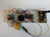
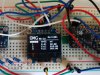
IMG_20161130_111309.jpg

IMG_20161130_111426.jpg

[video=youtube;ylzazZNkNJ4]https://www.youtube.com/watch?v=ylzazZNkNJ4[/video]

To do:
-a little bit coding (stopping blinking numbers, ...)
-Waterproof housing
-Testing

Does someone has a idea about a waterproof housing?
Thanks!
Best Regards
Anton
 
Interesting. I'd be interested to see how you're coding the ADC readings. I started to build a cell checker last summer, and couldn't get accurate readings from all 3 sensors simultaneously.

For a waterproof housing, check out the Hammond enclosures. There's a fellow over on RBW that built a whole ccr display/computer in one. I think it's in a DIY temp stick thread.

Jim


Sent from my iPhone using Tapatalk
 
Hello,
Thanks!
BUt the boxes are too bulky. The whole electronic is very small.
I think its possible to put it in a 8cmx5cm Box

about the code:
had a little help from a friend and its not finished yet.

Code:
 for(i=0;i<3;i++)
 {
    //start calibration
    calibrationv[i]=get_adc(i);
   if ((calibrationv[i] > Sensor_highrange) || (calibrationv[i] < Sensor_lowrange))
   {
     sensorcheck[i]=1;
     //TODO print sersor error
   } 
 }


 set_Display();
}


void loop(){

  double currentmv[3];
  double result[3];
  
  for(uint8_t i = 0; i<3; i++)
  {
    currentmv[i] = get_adc(i);
    result[i]=(currentmv[i]/calibrationv[i])*0.209;
  }
  int p = vcc.Read_Perc(VccMin, VccMax);
  
  display.clearDisplay();
  set_Display();


  display.setCursor(100,0);
  display.print(p);
  display.println("%");


  //set O2
  for(uint8_t i = 0; i<3; i++)
  {
    //display.setTextColor(WHITE);
    switch(i){
      case 0:
        display.setCursor(50,32);
      break;

      case 1:
        display.setCursor(50,42);
      break;

      case 2:
        display.setCursor(50,52);
      break;
    }
    if(sensorcheck[i])
      display.println("Fail");
    else
      display.print(result[i]);
  }

hope it helps

Regards
anton
 
Last edited:
Nice work!

I'm in the progress of putting one together too, using a SILabs Gecko instead of the AVR. I've gone a slightly different direction, chasing to fit the whole thing (including a AAA battery) in the HUD itself. It's been an interesting journey and the bulk of the hard stuff has been the enclosure - to keep things super tight I've made a mould and am injecting polyurethane as a combination of potting and case around the PCB.

Delrin is super popular for this kind of thing, if you have access to someone with a small CNC router they could belt out a box from a Delrin blank pretty quicksmart...
 
Hello,
Thanks!
BUt the boxes are too bulky. The whole electronic is very small.
I think its possible to put it in a 8cmx5cm Box

about the code:
had a little help from a friend and its not finished yet.

Code:
 for(i=0;i<3;i++)
 {
    //start calibration
    calibrationv[i]=get_adc(i);
   if ((calibrationv[i] > Sensor_highrange) || (calibrationv[i] < Sensor_lowrange))
   {
     sensorcheck[i]=1;
     //TODO print sersor error
   } 
 }


 set_Display();
}


void loop(){

  double currentmv[3];
  double result[3];
  
  for(uint8_t i = 0; i<3; i++)
  {
    currentmv[i] = get_adc(i);
    result[i]=(currentmv[i]/calibrationv[i])*0.209;
  }
  int p = vcc.Read_Perc(VccMin, VccMax);
  
  display.clearDisplay();
  set_Display();


  display.setCursor(100,0);
  display.print(p);
  display.println("%");


  //set O2
  for(uint8_t i = 0; i<3; i++)
  {
    //display.setTextColor(WHITE);
    switch(i){
      case 0:
        display.setCursor(50,32);
      break;

      case 1:
        display.setCursor(50,42);
      break;

      case 2:
        display.setCursor(50,52);
      break;
    }
    if(sensorcheck[i])
      display.println("Fail");
    else
      display.print(result[i]);
  }

hope it helps

Regards
anton
Hi, just a suggestion: use 100% oxygen for calibration or set new variable calibrationGass and maje it setable.
It is a bit more complex but much more accurate. Beside this check readings at high O2 ppo2 and at low ppo2 to see if any ADC offset present. It will help you understand why it is better to calibrate with 100% O2.
To make more stable readings try to implement running average...I use it with my teensy project to smoothen readings from sensors.

There is a lot more...but think basic things covered...

Sent from my LG-K420 using Tapatalk
 
^^ This. As a general rule it's best to calibrate somewhere close to where the thing will be operating, that way errors of scaling etc tend to have less impact.

Flickering numbers - running average is a great fix for this. You can weight the current value to improve responsiveness eg [ 5*s[0] + 2*s[1] + s[2] + s[3] ) / 9.0. When a sample comes in, you can either bunt the values through the array { for (int i=3; i>0; ) { s = s[--i]; } s[0] = latestSample } or, if you're squeezed for cpu cycles then look at a basic circular buffer for samples.

Doubtless there'll be plenty of this available as libs for Arduino already.
 
Well there are samples of running average on Arduino website. And described quite well. Think I saw a library for it too, but it is not that usable for our purpose.

Much better is arduino smooting sample. Simple to implement.

Sent from my LG-K420 using Tapatalk
 
Hello,
many thanks for the input!
I was thinking about 100% O2 calibration but for a fast test during the building i think its better with 21%. When everything is running fine, I'll try 100%.
I try to keep it supersimple: no buttons, only one on/off switch. The idea is switch it on and it calibrates, after that, ready for dive.

I'll try it with the flickering number solution - running average, Thanks!

Delrin is a good tip!
Delrin with a plexiglass cover.
Have to ask a friend if his cnc router is free.
First i have to do the circuit board with a good layout for a compact size.

Thanks!!
Best Regards
Anton
 
Just for clarification ..... Are numbers disapering and coming back - flickering or value is shifting up and down?

Sent from my LG-K420 using Tapatalk
 
Delrin + acrylic top = shearwater, av-uwtec, etc etc etc. Pretty tried and true combo. Bang a face o-ring in there and enough screws to keep the clamping force nice and even and you're in win city.
 
Hello igor,
i think its from the measuring and calculating...

Ill go the delrin and acrylic way.

Thanks!

Regards anton
 
Hello igor,
i think its from the measuring and calculating...

Ill go the delrin and acrylic way.

Thanks!

Regards anton
Ok, but I would still like to know if numb÷s are changing up and doun for small value or they disapear and reapear...
Two different things...

Sent from my LG-K420 using Tapatalk
 
Than it is a problem of code to display info on screen. Will check your code...

Sent from my LG-K420 using Tapatalk
 
Hello,
I tryed to find a x-link for my O²CCR but no luck, so i decided to bulid an arduino ppO² display.

Thanks!
Best Regards
Anton


If you want to build a duplicate X-Link, then it only need to add an IR component, on a UART port. The IR runs at a baud of 31250. It used to be a part called TIR1000, but you would need some replacement part now. Usually they need a clk of 16x baud.

I have the protocol and code that goes into the device that does the basic comms to the X1. Contact me if you wish to proceed. support@hhssoftware.com
 
And I am willing to share the original hardware project of the X-link updated with newer components (if they did not become obsolete in meantime). Got it from Eric time agoo.

If interested diverssi@yahoo.com
 
Last edited:
Hi,
Thanks for the offer Ross!
I think thats too big for me. I've only small knowledge about electronics and programming.

@Igor: I drop you a line. Thanks

Thanks!
BEst regards
anton
 
Back
Top